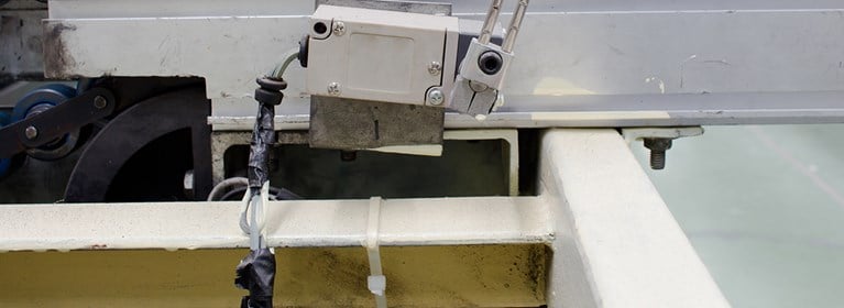
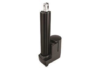
What is an actuator limit switch?
A limit switch is designed to stop the actuator from exceeding an extended or retracted length. Some Duff-Norton linear actuators have fixed limit switches, and some have adjustable limit switches that you can set depending on your application.
Why would you want a limit switch on your actuator?
A limit switch would prevent overtravel when the actuator is extended or bottoming out when the actuator is retracted. Adjustable limit switches are designed to stop the actuator at a predetermined point during extension or retraction.
How do you adjust a limit switch on a linear actuator?
Only some types of actuators have adjustable limit switches, and adjustment is different depending on the model and manufacturer. For example, Duff-Norton offers a variety of actuators with adjustable limit switches, including the LS Series, MPD Series, SPA Series, SPD Series, TAL Series, CMLA Series, and TMD Series, as well as SCW and SCN SuperCylinders. View the instructions below on how to adjust the limit switch on each linear actuator series.
Limit switches allow you to set the travel limits on your linear actuator in accordance with your application’s needs. In some instances, limit switches come pre-set but these default measures aren’t always suitable for your application.
If you need to manually set a limit switch on a linear actuator, there are a four simple steps to follow.
1. Retract the actuator
Very carefully run the actuator to the retracted or lowest position possible. Make sure you take into account the manufacturer’s advice on the minimum allowable retracted position before the product jams.
2. Adjust the limit switch
The type of limit switch will vary from product to product. You might have a travelling nut style, a rotating screw on a small thread or a disc that travels back and forth. Turn the nut or adjust the cam until the switch clicks. This means the switch is set at that extreme position.
LS Series
- A. Temporarily connect power, per the appropriate wiring diagram. Run actuator in the “Retract” direction until stopped by the limit
switch. Rotate translating tube until the pin-to-pin dimension of the clevis holes match the installed, fully retracted position. Translating
tube should not be fully retracted against internal stop. At least 1/4” of overtravel allowance is recommended.
- B. With the translating tube restrained against rotation, run the actuator to the desired extended position.
- C. Disconnect power. Remove round limit switch cover.
- D. Loosen the flat head screw in the middle of the round plastic cam. Loosen screw about three turns – complete removal is not required. Rotate the cam counterclockwise until the limit switch just clicks. Hold the cam in this position and retighten screw.
- E. Restore power and, with the translating tube restrained from rotation, operate the actuator to check limit switch setting.
- F. If settings are correct, disconnect power and reinstall round cover.
- Note: moving the cam one notch changes limit switch setting
about 4mm (5/32”).
Notes:
1.Exercise care to avoid jamminig the actuator.
2.With no load, some actuator drift is typical. If precise setting is required,
it must be done with the expected operating load.
MPD and SPD Series
- Set Retract Position
- a. Do not connect translating tube to work piece at this time.
- b. Energize and retract actuator until gear cam opens limit switch.
Note: Translating tube may have to jam and spin prior to switch activation.
-
- c. Unscrew the translating tube until the measured distance between the housing clevis hole centerline and the translating tube clevis hole centerline equals the desired closed height. If the mating clevis holes are not aligned, manually rotate the translating tube to align the clevises, this will be less than 180˚ rotation and the closed height of the actuator will then be within 1/4” of the desired retracted dimension.
- d. Pin the translating tube clevis in place and energize the actuator to check the drift.
- Set Extend Position
- a. Restrain the translating tube from turning, operate actuator and extend to desired position.
- b. Adjust steel switch cam until switch is activated allowing for drift. (This is accomplished by loosening socket head set screw until cam rotates with a slight drag on the shaft when the Allen wrench is used as a lever.)
- c. Check travel and readjust if necessary.
- d. Socket head set screw on cam should be
tightened after final adjustment is made. Do not strip threads by overtightening. At maximum load, repeatability is 1/8” in either direction including drift and normal wear of parts.
SPA Series
- Setting Retracted Position
- a. Do not install actuator in the intended application at this time.
- b. With nut retainer “A” installed in actuator and the translating tube unstrained, operate actuator toward retracted position until limit switch nut “B” trips limit switch.
Note: Translating tube may jam and rotate prior to tripping limit switch.
-
- c. Rotate the translating tube by hand until distance between the housing clevis hole centerline and the translating tube clevis hole
centerline equals the desired closed height. This centerline to centerline dimension is not to be less than the retracted centerline to centerline dimension listed in Figure 1-6. If the two clevis end holes are not oriented as required, rotate the translating tube no more than 1/2 turn in either direction until they are properly oriented.
- d. Install actuator in application and check drift. Slight readjustment in switch actuation may be attained by removing nut restrainer “A” and rotating limit switch nut “B” (1 notch of rotation = .05 in. of screw travel). Replace nut restrainer, “A”
- 2. Setting Extended Position
- a.Restrain the translating tube against rotation by hand. Operate the actuator, toward the extended position, until the distance between the housing clevis hole centerline and the translating tube clevis hole centerline equals the desired extended height. This centerline to centerline dimension is not to exceed the extended centerline to centerline dimension listed in Figure 1-6.
- b. Remove nut restrainer “A” and rotate limit switch nut “C” (see Figure 6-3) until it activates the limit switch.
- c. Replace nut restrainer “A”.
- d. Install actuator in application and check the unit's drift. Slight readjustment in switch actuation may be attained by removing nut
restrainer “A” and (1) rotating limit switch nut “B” to adjust retracted position or (2) rotating limit switch nut “C” to adjust extended position (1 notch of rotation = .05 in. of screw travel).
- e. After adjusting limit switch nuts, replace nut restrainer “A”. Operate the actuator and readjust limit switch nuts as necessary to achieve desired travel.
TAL Series
- With translating tube unrestrained, run the actuator toward the retracted position until the switch cam actuates the switch.
- Rotate the translating tube by hand to the desired retracted position.
- With the translating tube restrained against rotation, run the actuator to the desired extended position.
- Disconnect power. Remove motor cover. On Potentiometer models only: remove two screws holding the terminal block plate and pull plate and potentiometer straight off, firmly holding limit switch cams.
- Raise the flap of the electrical insulator sheet to expose the limit switch cams. Holding the cam gear to prevent loading of the small gears, loosen the two screws holding the top cam. Rotate the cam toward
the switch until the switch just clicks. Again holding the gear, tighten the screws.
- Restore power and operate actuator to check limit switch settings.
- If settings are correct, disconnect power and reinstall
motor cover.
CMLA Series
Limit functions are provided by a programmed memory chip inside the actuator. The limits are factory set at their extremes of stroke. Limit positions may be permanently reprogrammed with the following procedure.
- Remove the hex socket hole plug on the top of the actuator housing, near the cable entry.
- Use the small insulated screwdriver supplied with actuator to turn the selector switch, visible in the hole, to Position 1 (full counterclockwise).
- Run the actuator to the position desired for retracted limit stop.
- Turn the circuit board switch to Position 4 (full clockwise).
- Run the actuator to the position desired for extended stop.
- Turn the same switch to Position 2 (two clicks CCW).
- Operate actuator to check new limit positions.
- Replace hole plug.
TMD Series
Actuators with factory installed switches are shipped with switches adjusted for maximum retraction and travel. Attempting to increase stroke in either direction invites actuator jamming which will result in irreparable damage. Stroke may be reduced on either end of travel by loosening screws attaching
switches, sliding along tube, and resecuring.
SCN and SCW SuperCylinders
Limit switches (if fitted) are not factory set and must be adjusted to prevent jamming and damage to the actuator and/or mating equipment.
- Before setting limit switches, the installer should make certain that the actuator has sufficient travel in both directions to produce the range of travel required by the installation. If there is any question about this, the rod end clevis pin should be disconnected and the rod rotated by hand, in each direction, to its internal stops. The length of extended
rod can be measured in these two extremes and the measurements used for reference while setting limit switches.
- Remove limit switch cover. With the clevises connected, jog actuator to its retracted position, making sure that the rod is extended at least 1/2” from the jam closed position. Observe white plastic limit switch nuts and be sure that neither one travels into a switch. If contact is imminent, disconnect power and screw nut away from switch, as described in the next paragraph.
- Refer to Figure 1 for limit switch nut identification. Remove the screw “A” and nut guide “B”. Rotatethe “retract” nut toward the switch until the switch just clicks. Rotate nut 1/2 turn (5 slots) farther (to allow for drift), and install nut guide.
- Restore power and jog the rod out for a few seconds, then retract it until it is cut off by the limit switch. If fine adjustment is needed, disconnect power, move nut one or two slots at a time and recheck.
The amount of drift can vary widely on Acme screw models without brakes. On these models, drift will, in general, be greater under light loads. When setting limit switches, it is best to operate Acme screw
models at lightest expected load, and to operate ball screw models at greatest expected load.
- Jog actuator to its extended position, repeating all the steps from paragraphs 2-4 for the “extend” switch and nut.
3. Extend the actuator
Carefully run the actuator to the opposite extreme, again referring to the manufacturer’s advice.
4. Adjust the limit switch again
As before, adjust the nut or cam until the switch clicks. This will set the limit switch at the upper most extreme.
Checking the limit switch
Setting a limit switch can be a simple job if you take the necessary precautions and follow the steps above closely. It’s important to make sure you know which switch corresponds to which direction of travel, so always consult with your manufacturer if you are unsure.
Once you’ve set the limit switch on your linear actuator, run the application to check for drift in any direction. If the product runs smoothly you have successfully set the limit switch.
North America - EN


