,fit=pad/globalassets/logos/camlok/new/camlok-10.11.svg)
,fit=pad/globalassets/logos/cm/new/cm_color-10.11.svg)
,fit=pad/contentassets/1f4eac3541654db5a396d6c67f7ce0fb/crosby_red_rgb.png)
,fit=pad/globalassets/logos/dixie/new/dixie_industries_color-10.11.svg)
,fit=pad/globalassets/logos/dorner/new/dorner_color-10.11.svg)
,fit=pad/globalassets/logos/duff-norton/new/duff-norton_color-10.11.svg)
,fit=pad/globalassets/logos/garvey/new/garvey_color-10.11.svg)
,fit=pad/contentassets/8c25a81873f3447490ffdc9d9b53f5f5/kito_black.png)
,fit=pad/globalassets/logos/little-mule/new/little_mule_color-10.11.svg)
,fit=pad/globalassets/logos/magnetek/new/magnetek_wide_color-10.11.svg)
,fit=pad/globalassets/logos/pfaff/new/pfaff_color-10.11.svg)
,fit=pad/globalassets/logos/shaw-box/new/shaw-box_color-10.11.svg)
,fit=pad/globalassets/logos/stahl/new-by-cmco/stahl_color-10.11.svg)
,fit=pad/globalassets/logos/steerman/new/steerman_color-10.11.svg)
,fit=pad/globalassets/logos/unified/new/unified_color-10.11.svg)
,fit=pad/globalassets/logos/yale/new/yale-10.11.svg)
 North America - EN
,fit=pad/globalassets/logos/camlok/new/camlok-10.11.svg)
,fit=pad/globalassets/logos/cm/new/cm_color-10.11.svg)
,fit=pad/contentassets/1f4eac3541654db5a396d6c67f7ce0fb/crosby_red_rgb.png)
,fit=pad/globalassets/logos/dixie/new/dixie_industries_color-10.11.svg)
,fit=pad/globalassets/logos/dorner/new/dorner_color-10.11.svg)
,fit=pad/globalassets/logos/duff-norton/new/duff-norton_color-10.11.svg)
,fit=pad/globalassets/logos/garvey/new/garvey_color-10.11.svg)
,fit=pad/contentassets/8c25a81873f3447490ffdc9d9b53f5f5/kito_black.png)
,fit=pad/globalassets/logos/little-mule/new/little_mule_color-10.11.svg)
,fit=pad/globalassets/logos/magnetek/new/magnetek_wide_color-10.11.svg)
,fit=pad/globalassets/logos/pfaff/new/pfaff_color-10.11.svg)
,fit=pad/globalassets/logos/shaw-box/new/shaw-box_color-10.11.svg)
,fit=pad/globalassets/logos/stahl/new-by-cmco/stahl_color-10.11.svg)
,fit=pad/globalassets/logos/steerman/new/steerman_color-10.11.svg)
,fit=pad/globalassets/logos/unified/new/unified_color-10.11.svg)
,fit=pad/globalassets/logos/yale/new/yale-10.11.svg)
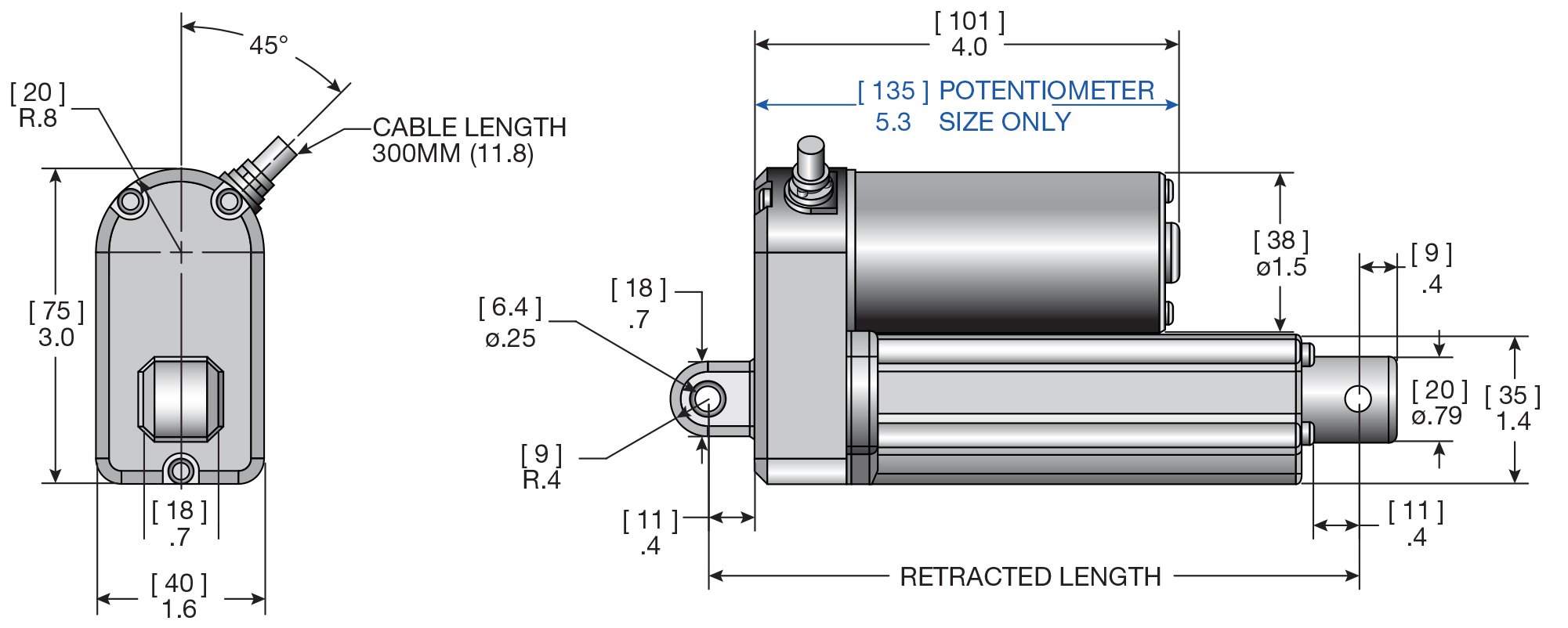
LT Series - 27 to 225 lbs


The LT Series is a type of electric actuator designed for heavy-duty applications that may be exposed to harsh environments. These actuators are built to withstand challenging conditions.
Documents
Need Assistance?
Not sure if this is the right product for your application, or need a custom solution? Contact us today for help from an expert.
Documents
Documents
Brochures & Catalogs
Manuals & Supplements
Product & Data Sheets
Product Diagrams
Product Diagrams
|
LT Series Dimensions
|
|---|
Linear Actuator System Controls |
||
|---|---|---|
|
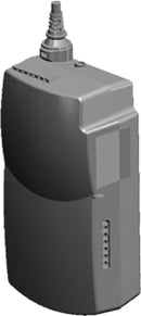
TC1 Control Box |
LTEC |
Features and benefits |
|
|
|
|
Synchronized Linear Actuator systems |
||
|---|---|---|
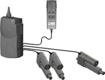
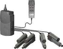
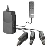
| The Duff-Norton linear actuator system will allow you to synchronize two linear actuators and control up to another two linear actuators independently. A Duff-Norton linear actuator system includes linear actuators, a controller and a hand set for operation. System applications can include agricultural machinery, industrial automation and outdoor power equipment. | ||
|
Two Synchronized |
Two Synchronized - One Independent |
Two Synchronized - Two Independent |
| Part No. TH1-121-2016S | Part No. TH1-321-2016S | Part No. TH1-421-2016S |
 |
 |
 |
|
Model Number |
Description |
Feature |
Feature |
Other |
| See LT models | Actuator | 24 VDC models only | Hall Sensor models only (add H suffix to part number) | any capacity or stroke length |
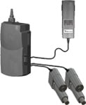
| TC1-2241-1221 | Controller | 120 VAC power in - 82" cord | 24 VDC power out | 1 per system |
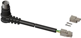
| NA | Actuator Extension Cable 40" | NA | NA | NA |
| See image above | Handset | partial coiled wire | extends to approx. 7 foot length | 1 per system |
|
Please do not exceed 10% of 2 minutes continuous use duty cycle with these systems. Exceeding these rates might result in a temporary suspension of service. The system should operate again after a brief cooling period. For synchronized operation please select the Hall Sensor models only. Models with no feedback, or the potentiometer may be used for independent operation, and will require the LTEC kit. |
||||
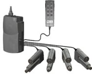
Linear Actuators Controlled Independently |
|||||||||||||||||||||||||
|---|---|---|---|---|---|---|---|---|---|---|---|---|---|---|---|---|---|---|---|---|---|---|---|---|---|
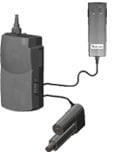
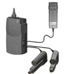
| The Duff-Norton linear actuator system will allow you to control up to four linear actuators independently. A Duff-Norton linear actuator system includes linear actuators, a controller and a hand set for operation. System applications can include agricultural machinery, industrial automation and outdoor power equipment. | |||||||||||||||||||||||||
Click here to download a PDF with larger images. |
|||||||||||||||||||||||||
Please do not exceed 10% of 2 minutes continuous use duty cycle with these systems. Exceeding these rates might result in a temporary suspension of service. The system should operate again after a brief cooling period. For synchronized operation please select the Hall Sensor models only. Models with no feedback, or the potentiometer may be used for independent operation, and will require the LTEC kit. |
Related Products