By DUFF-NORTON | May 08, 2019
The lifting torque for a single actuator depends on the load, the worm gear ratio, type of screw (machine cut or ball screw) and the pitch of the lifting screw. Torques are listed in the specification chart based on capacity loads. For loads from 25% to 100% of actuator model capacity, torque requirements are approximately proportional to the load.
Perhaps the greatest single advantage of Duff-Norton actuators is that they can be tied together mechanically, to lift and lower in unison. See typical arrangements involving the actuator units, mitre gear boxes, motors, reducers, shafting and couplings.
This will be limited by the input torque requirements on the first worm shaft in the line. The torque on the worm shaft of the first actuator unit should not exceed 300% of its rated full load torque based for most machine screw models. Torque can be reduced by using a double end gear motor at the center of the arrangement or a higher capacity actuator model can be used as the first unit in the line, provided the turns for 1” raise are the same as the lower capacity units. If this is not possible, the actuators may be individually motorized and synchronized using electronic controls.
The input horsepower to these actuators should not exceed the hp rating shown in the specifications tables. Maximum RPM should not exceed 1800. We cannot accept responsibility for the overheating and rapid wear that may occur should these limits be exceeded. Horsepower increases in direct proportion to the speed, and the motor size will be out of proportion to the actuator model design rating should the speed become excessively high. When selecting the maximum permissible speed for an actuating arrangement, always check to see that the hp rating of the actuator model is not exceeded
The gear boxes can be run at the same speeds as the actuator models. Do not exceed torque ratings.
Actuator model efficiencies are listed in the following specification charts:
Note: Where both starting and running torques are listed, use the running torque for hp calculations when using induction electric motors.
We use 98% efficiency.
In addition to the efficiencies of the actuator units and the mitre gear boxes, the efficiency of the actuator multiple-unit arrangement must be taken into consideration. The arrangement efficiency allows for misalignment due to slight deformation of the structure under load, for the losses in couplings and bearings, and for a normal amount of misalignment in positioning the actuators and gear boxes. We use the following efficiencies (all standard units):
A recommendation should be obtained from the Duff-Norton Company on this type application contact a Duff-Norton Application Engineer for clarification. In general, semi- continuous operation can be permitted where load is light as compared to actuator model rated capacity. Units so used should be lubricated frequently and protected against dust and dirt. The Duff -Norton 7500 Series, oil-lubricated, Continuous Duty cycle actuator is designed for maximum duty cycles.
Generally, standard raises are up to 12 inches on 1/4 and 1/2 ton models and 18 inches on the 1 Ton. Maximum raises available for the larger diameter screws are limited only by the available length of bar stock from suppliers. Practical length will be affected by whether the screw is to be subjected to compression or tension loads. Depending on diameter, the length can be limited due to deformation of material in the machining process or column strength of the screw when subjected to compression loads. Long raise applications should be checked with Duff-Norton for the following:
We suggest guides be used on all applications. The longer the raise, the more important this becomes.
Actuator units are designed primarily to raise and lower loads and any side thrust should be avoided. These units will withstand some side thrust, depending on diameter of the screw and the extended length of the screw. Where side thrusts are present, the loads should be guided and the guides, rather than the actuator units, should take the side thrust - particularly when long raises are involved. Even a small side thrust can exert great force on the housings and bearings and increase the operating torque.
The column strength of a screw is determined by the relationship between the length of the screw and its diameter. A column strength nomograph is included in this book on page 100.
The duty cycle, the length of the screw, the magnitude of the load, and the efficiency of the actuator unit all have a direct influence on the amount of heat generated within the actuator model. Since most of the power input is used to overcome friction, a large amount of heat is generated in the worm gear set in both ball screw and machine screw actuator models, and in the lifting screw of machine screw actuator units. Long lifts can cause serious overheating.
Because of the low efficiency of worm gear actuators, the duty cycle is low at rated load. At reduced loading, the duty cycle may be increased. Contact Duff-Norton for more complete information.
The life of a machine screw actuator screw, nut and worm gear set varies considerably due to extent of lubrication, abrasive or chemical action, overloading, eccentric loading, excessive heat, improper maintenance, etc.
Yes, although the Duff-Norton SuperCylinder is recommended for these applications due to stroke limitations with the conventional double clevis configuration. Double clevis actuators are furnished with a clevis at both ends. The bottom clevis is welded to the bottom end of an extra strong pipe which is threaded into the base of the actuator and welded. This bottom pipe still performs its primary function of encasing the lifting screw in its retracted position. The design of the structure in which this type unit is to be used must be so constructed that the actuator unit can pivot at both ends. Use only direct compression or tension loads, thereby eliminating side thrust conditions.
We recommend that the actuator selected have a greater capacity than the rated capacity of the press or of the load capacity of the structure. We also recommend that a torque limiting clutch or similar device be used to prevent overloading of the actuator unit. Unless these precautions are taken, it is possible to overload the actuator unit without realizing it, because it is difficult to determine just what load is being imposed on the actuator unit.
Yes, except for the ball screw (where we use a square nut on the end of the screw and a square tube to prevent screw rotation); however, the keyway in the screw causes greater than normal wear on the internal threads of the worm gear. The ball screw cannot be keyed, as the keyway would interrupt the ball track, permitting loss of the recirculating balls. We also recommend the following methods for preventing rotation. For multiple actuator model applications, bolt the lifting screw top plates to the member being lifted. For single actuator unit applications, bolt the lifting screw top plate to the load. And the load should be guided to prevent rotation.
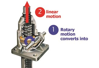
When an actuator unit is operated, the rotation of the worm shaft causes the worm gear to rotate. The worm gear is threaded to accommodate the lifting screw thread; as the worm gear turns, the friction forces on the screw thread act to turn the screw also. The greater the load on the actuator unit, the greater the tendency of the screw to turn. It is obvious that if the screw turns with the nut (worm gear), it will not raise the load. In those cases where a single unit is used, and where the load cannot be restrained from turning, it is necessary to key the lifting screw. The lifting screw turning movement or key torque is shown in the specifications charts listed in Question 6.
Yes, but the key is mounted in the shell cap, making it necessary to omit the dust guard as a standard item. If a dust guard is required, a special adaptor must be attached to permit mounting.
Yes, but allowance must be made in the length of the lifting screw for both the closed height of the boot and structure thickness. Since we can make no provision for attaching a boot on the underside of your structure, we suggest that a circular plate similar to the lifting screw top plate be welded or bolted to the bottom of your structure supporting the actuator unit, thereby making it possible to use a standard bellows boot. See Accessories - Bellows Boots.
Stop disc, pins or nuts can be recommended on the actuator unit that is hand operated. For motor driven units, the full capacity of the actuator unit or even a greater force (depending on the power of the motor) can be applied against the stop, thereby jamming so tightly it must be disassembled in order to free it. It is suggested that external stops be used where possible. Under ideal conditions where a slip clutch or torque limiting device is used, a stop pin or stop nut may be used - but the Duff-Norton Company should be consulted. The stop disc used on the bottom of the lifting screw in our ball screw units are not power stops. These are used to ensure that the lifting screw will not run out of the ball nut during shipping and handling, thereby permitting loss of the recirculating balls.
Shock loads should be eliminated or reduced as much as possible, but if they cannot be avoided, the actuator model selected should be rated at twice the required static load. For severe shock load applications, using machine screw models, the load bearings should be replaced with heat-treated steel thrust rings which will increase the lifting torque approximately 100 percent. These rings are available as a special from Duff-Norton.
Only machine screw and anti-backlash models with 24:1 and 25:1 ratios are self-locking in most cases. Other machine screw and anti-backlash models with 12:1 lower ratios are not self-locking. All ball screw models are not self-locking. Units considered not self-locking will require a brake or other control device. If vibration conditions exist, see question 25.
Yes, but vibration can cause the lifting screw to creep or inch down under load. For applications involving slight vibration, select the higher of the worm gear ratios. Should considerable vibration be present, use a drive motor equipped with a magnetic brake which will prevent the actuator model from self-lowering.
Yes, unless a brake of sufficient capacity is used to prevent it. The amount of drift will depend upon the load on the actuator unit and the inertia of the rotor in the motor. Most Machine Screw models require approximately one-half as much torque to lower the load as it does to raise the load. For the machine screw actuator unit with no load, the amount of drift will depend upon the size and speed of the motor. For example, a 1750 RPM motor directly connected to an actuator unit (without a load) will give on the average 2”- 3” drift; a 500 RPM gear motor will give about 1/9 as much drift. Note that the drift varies as the square of the velocity (RPM). The drift of the actuator unit screw can be controlled by using a magnetic brake on the motor.
The lifting torque, as well as the efficiency and side thrust ratings, are the same for a rotating screw unit. It is understood, however, that the same pitch and screw diameter are used in each actuator unit, as well as the same worm gear ratio. This comment also applies to the inverted actuator unit and those with threaded or clevis-style ends.
The actuator is normally suitable for operation at ambient temperatures of up to 200°F using standard greases and seals. Operation above 200°F will require special lubricants. For temperatures above 300°F the life of even special lubricants is limited in direct proportion to increase in temperature and duration of exposure to such temperatures. At 400°F and above, the oil in the grease will vaporize and grease will carbonize and solidify. Applications of this type should be avoided. For temperatures above 250°F advise Duff-Norton of full particulars of the duration of such temperatures. In some cases, it may be necessary to furnish unlubricated units, then the customer will supply the lubricant of his own choice. We suggest that a lubricant manufacturer be consulted for type of grease and lubrication schedule. As a general rule, the actuator unit should be shielded to keep ambient temperatures to 200°F or less. Seals for temperatures above 250°F are very expensive. Instead, we would substitute bronze bushings for seals in these cases. If bellows boots are used, special materials will be required for temperatures above 200°F
With the standard lubricant and materials of construction, the actuator is suitable for use at sustained temperatures of 0°F. Below 0°F, low temperature lubricant should be used. Also, at temperatures below 0°F, if there is any possibility of shock loading, special materials may be required due to notch sensitivity of the standard materials at lower temperatures. Duff Norton factory application engineers must be consulted in these instances for a recommendation. Actuators with standard materials of construction and lubrication may be safely stored at temperatures as low as -65°F.
The machine screw, anti-backlash and Ball Screw models must be considered separately, as the normal backlash will vary due to different constructions. For the machine screw models there is a normal backlash of .005” to .008” in the lifting screw thread, plus .002” to .003” backlash in the load bearings. Therefore, the total backlash is .007” to .011”. This backlash is due not only to normal manufacturing tolerances, but to the fact that we must have some clearances to prevent binding and galling when the actuator unit is under load. Usually, the backlash is not a problem unless the load on the actuator unit changes between compression and tension. If a problem does exist, then an anti-backlash model should be considered.
Anti-backlash models: This unit can be adjusted for screw thread and bearing clearances to a minimum of .0005”. Some clearances must be maintained to keep torque requirements within reason. As the inside thread of the worm gear and the anti-backlash nut wears, adjustment can be maintained by tightening down on the shell cap. Setscrews located in the top of the shell cap are to be respotted each time an adjustment is made. The additional nut used in the anti-backlash actuator unit is a built-in wear indicator. The clearance between the two nuts is designed to be 50 percent of the thread thickness. When all this adjustment is used, it indicates the point where the worm gear and the anti-backlash nut set is to be replaced.
Ball screw models will have a normal backlash of .002” to .013” between the ball nut and the ball track; .002” to .003” backlash in the load bearings. Total backlash will be .004” to .016”. As machine screw models, this backlash will not be detrimental unless the load changes between compression and tension, or tension and compression.
The worm gear and the anti-backlash nut are pinned together with guide pins. The threads in the anti-backlash nut work in opposition to the worm gear on the threads of the lifting screw. Adjustment is made by threading in the shell cap of the actuator unit, which forces the anti-backlash nut threads into closer contact, reducing clearance and thus reducing backlash. See How Anti-backlash Works.
Machine screw and anti-backlash model lift screws may have lead error up to .0008 per inch. It is cumulative and not detrimental to the operation of the actuator model. Ball screw models use heat treated rolled ball track with a lead error up to .003 per inch.
When the worm shaft speed is known, the distance the load can be raised per minute can be determined with this formula:
Raise per minute = RPM of Worm Shaft/
Turns of worm for 1” raise
or Travel per Worm Turn (mm) x RPM of Worm Shaft (Worm turns for 1 inch raise are shown in actuator specifications charts listed in Question 6.
If the application calls for a certain raise per minute, the worm shaft speed which will give the rate of raise can be calculated as follows:
Worm shaft RPM = Desired Rate of Raise (in/min) /
Worm Turns for 1” Raise
For metric actuators:
RPM = Desired Rate of Raise (mm/min) /
Travel per worm Turn (mm)
It is suggested that the actuator unit be purchased with the limit switch factory mounted. The rotary limit switch can be field mounted by following the instructions found in this book under “Rotary Limit Switch.” In most cases, the switch is mounted to the worm using the worm flange retainer bolts. This switch cannot be directly mounted on 1/4 to 1 ton actuator models.
Maximum raise is determined by the ratio of the switch used and the turns for one inch raise of the actuator unit. The limit switch ratios available are 10:1, 20:1 and 40:1. These can be found on the inside cover of the limit switch, and then use the following formula.
Max. Raise of Actuator Unit (inches) = Max. Input Revolutions of Limit Switch Turns of Actuator Unit Worm for 1 inch raise
The Duff-Norton rotary limit switch is infinitesimally adjustable by moving the adjustable nuts of the worm driven screw.
Yes, in several ways. However, it is suggested you consult Duff-Norton for recommendations based on your particular application.
Contact Our Engineering Team For A Free Application Analysis
Learn everything you need to know about the screw jacks available from Columbus McKinnon including the two types of screw jack systems, the main types of screw jacks (machine and ball) and, available features (stainless steel, anti-backlash, ,heavy-duty and more).


 North America - EN


